Practical 3 - Elements of solution
This page provides elements of solution for the Hierarchical Modeling practical. The scene graph with the base and arm only is detailed. Addition of the forearm is left as exercise.
What is this cylinder?
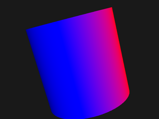
The Cylinder class loads the cylinder.obj mesh file. Peek at this file to see its structure. You will see for all vertices their coordinates (v), texture coordinates (vt), and normal (vn); followed by the triangles (f) indexes. Vertex coordinates reveal that:
the cylinder is aligned along the Y axis
its radius is 1
it height is 2 with the lower base on y = -1 and the upper one on y = +1. The cylinder is then centered on the origin.
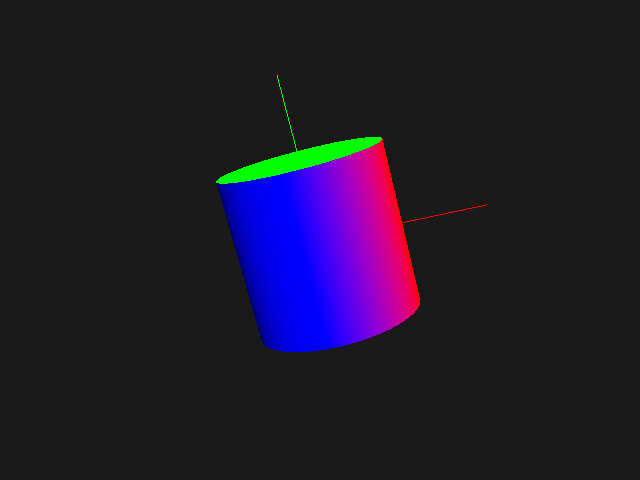
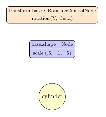
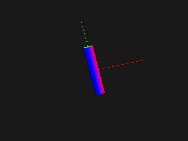
Here are two views of the cylinder mesh at scale factor 1 and then 0.5, along with the world referential axis:
Note
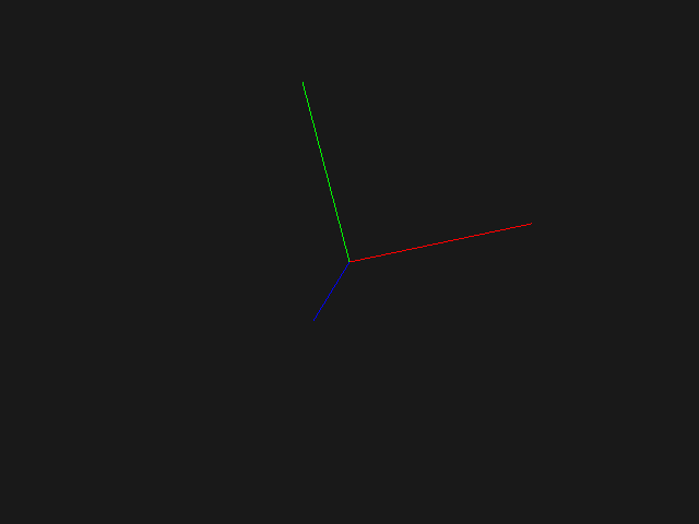
The RGB axes (X in red, Y in green, Z in blue) are normalized, with a length of 1. Use the class Axis with a flat color shader to add them in your scene.
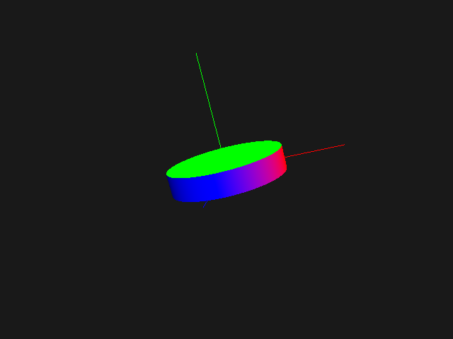
Step 0: base
A node is simply created with a scaling transform to have a flat cylinder; its single child is the original Cylinder instance. A parent RotationControlNode enable to turn the base around the Y axis.
cylinder = Cylinder(shader)
theta = 35.0        # base horizontal rotation angle

base_shape = Node(transform=scale(.5, .1, .5))
base_shape.add(cylinder)
transform_base = RotationControlNode(glfw.KEY_LEFT, glfw.KEY_RIGHT, (0, 1, 0), angle=theta)
transform_base.add(base_shape)

viewer.add(transform_base)
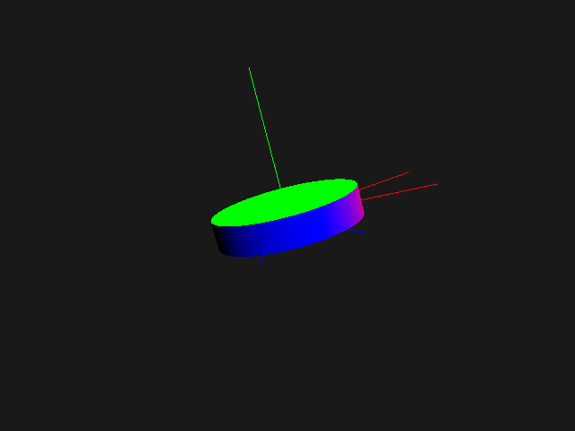
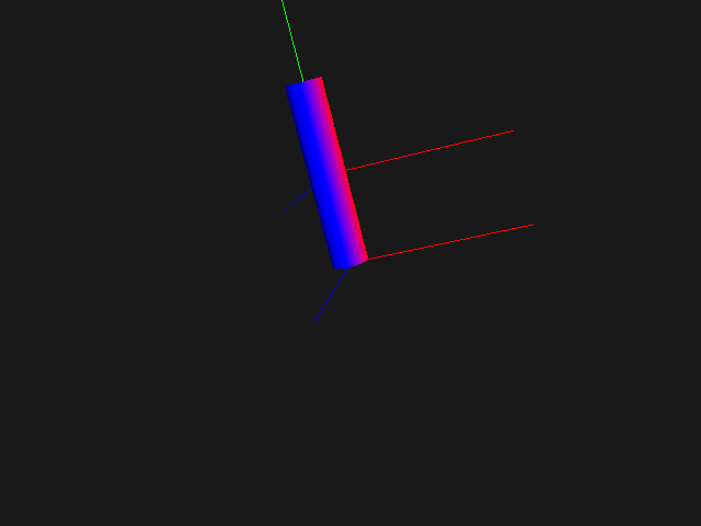
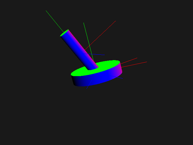
The images below show the base at each node, after scaling then after scaling and rotation (for clarity, the base referential is display with axes of length 1, not scaled). On the right, the base scene graph.
Which transforms are applied, in which order?
In exercise 1 the model matrix of a node was first combined with the node’s transform, then passed to the node’s children.
class Node:
    ...
    def draw(self, projection, view, model):
        """ Recursive draw, passing down updated model matrix. """
        self.world_transform = model @ self.transform
        for child in self.children:
            child.draw(model=self.world_transform, **other_uniforms)
For a given node:
modelis the pose of its parent in the world referential. For a hierarchy root node,modelis either the identity or the position of the whole object.self.transformis the pose of the node with respect to its parentself.childrenis the list of children, geometries or other nodes, which pose is defined relatively to the current node
The order of this transform combination is of most importance! The combination model @ self.transform means that self.transform is first apply to each child, and then model is applied.
For the base cylinder above, the model transform passed to the transform_base is by default the identity. Thus, the total transform applied (in the vertex shader) to each vertex of the cylinder is:
// in pseudo-code GLSL code
gl_Position =
    projection * view * identity * rotation((0, 1, 0), theta) * scale(.5, .1, .5) * vec4(position, 1);
Note
The order of transforms multiplication is fundamental. Two ways (at least) are possible in terms or reasoning: in terms of a Grand, Fixed Coordinate System or via a Moving a Local Coordinate System
This is well explained in the (old) first OpenGL book, a.k.a. “The red book”. Go to chapter 3 and search for “Thinking about Transformations”. Functions of the good-old fixed pipeline are not the same, but you will get the point.
Step 1: arm
Now we can create the arm:
phi1 = 25.0         # arm angle

arm_shape = Node(transform=translate(0, .5, 0) @ scale(.1, .5, .1))
arm_shape.add(cylinder)
rotation_arm = RotationControlNode(glfw.KEY_PAGE_UP, glfw.KEY_PAGE_DOWN, (0, 0, 1), angle=phi1)
rotation_arm.add(arm_shape)

viewer.add(rotation_arm)
With a scale only, the cylinder is still centered on the origin. Thus, it is then translated along the Y axis (note that the translation length must include the scaling factor! Only 0.5 here, not 1).
The translation and scaling are here combined in the node’s transform, but you could also use two different nodes.
Finally, a parent
RotationControlNodeenables to incline the arm. The rotation is centered on the (parent) control node referential, not on the (child) cylinder referential.
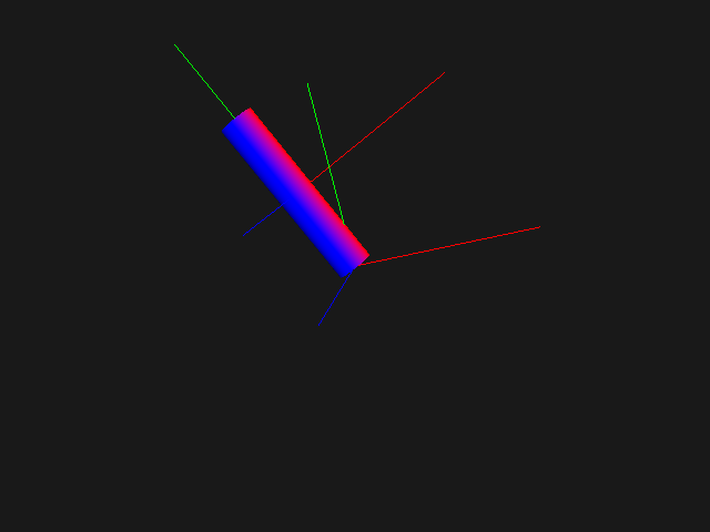
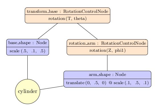
The arm scene graph is:
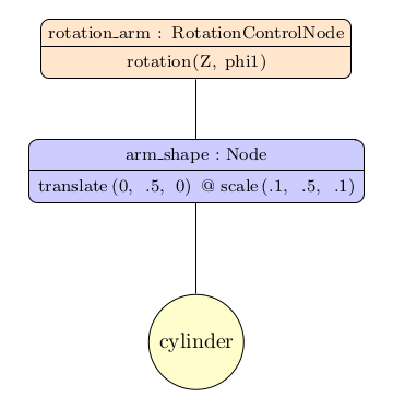
Step 2: final scene
If we simply add the two objects transform_base and rotation_arm in the viewer, there are two problems:
the arm is not correctly oriented (not affected by the base rotation of angle theta)
when the base is turned, the arm is not moved accordingly
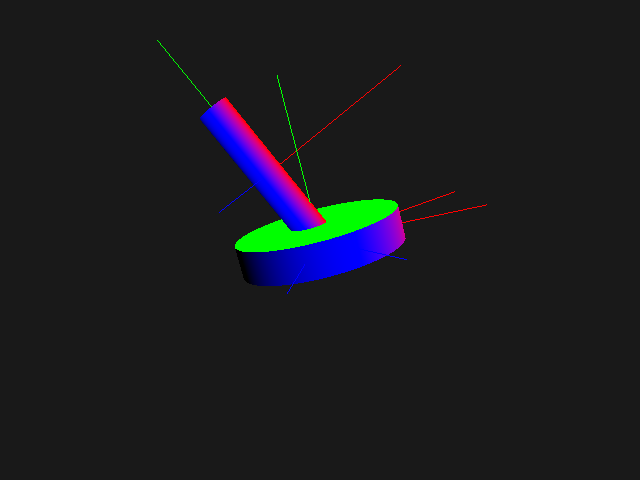
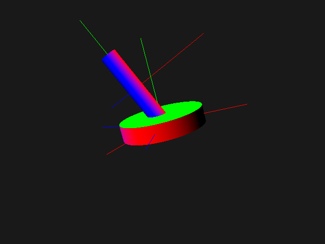
Thus we just have to link the two objects, the arm being a child node of the base:
transform_base.add(rotation_arm)

viewer.add(transform_base)  # only this root node is added to the viewer
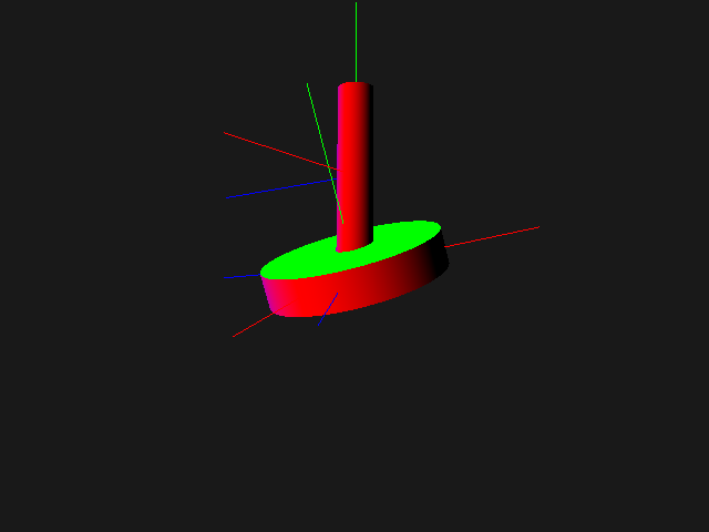
Below are the final code and scene graph. Note that a single instance of Cylinder is shared by the two branches.
cylinder = Cylinder(shader)
theta = 35.0        # base horizontal rotation angle
phi1 = 25.0         # arm angle

base_shape = Node(transform=scale(.5, .1, .5))
base_shape.add(cylinder)

arm_shape = Node(transform=translate(0, .5, 0) @ scale(.1, .5, .1))
arm_shape.add(cylinder)

rotation_arm = RotationControlNode(glfw.KEY_PAGE_UP, glfw.KEY_PAGE_DOWN, (0, 0, 1), angle=phi1)
rotation_arm.add(arm_shape)

transform_base = RotationControlNode(glfw.KEY_LEFT, glfw.KEY_RIGHT, (0, 1, 0), angle=theta)
transform_base.add(base_shape)
transform_base.add(rotation_arm)

viewer.add(transform_base)  # only this root node is added to the viewer
Note
Now it’s you turn!
To make sure everything is understood, add a forearm to this scene!